Personal project
Animatronic Eye Mech
- Problem
- Design a fully 3D-printed, compact animatronic eye driven by an Arduino and servo motors.
- Date
- Feb – Mar 2026
- My role
- Personal project: research, SolidWorks design, printing, assembly and Arduino code
- Size
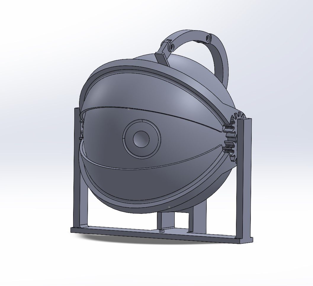
- 80 × 84 × 59 mm with the servo stand (about 3 in at the base); Ø64 mm eyeball
- Tools
- SolidWorks, Bambu Lab A1 (PLA), Arduino C++, two SG90 micro servos
- Result
- Working eye (iteration 3, joints repaired) that blinks and looks left and right
Approach
- Researched existing eye mechs and brainstormed ideas to make them more compact. Prioritized mounting the servos within the eye, making the design self-contained.
Design
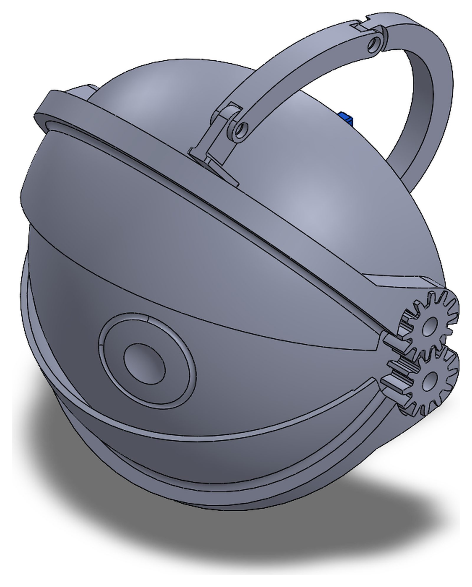
- Eye movement: the eyeball needed to look left and right.
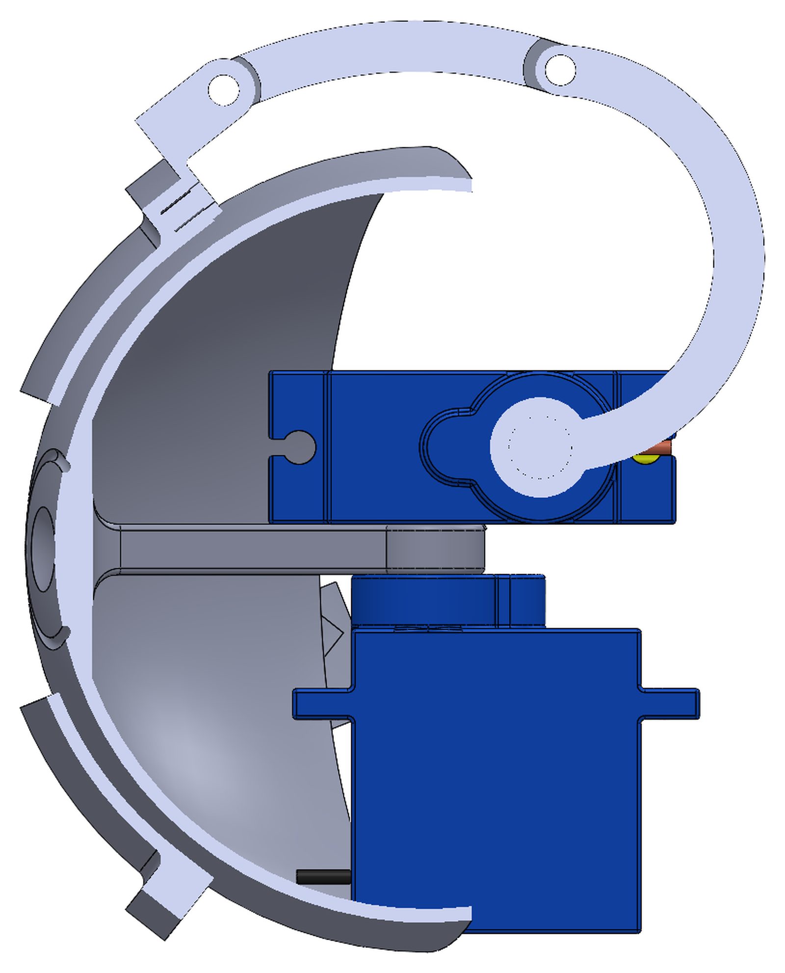
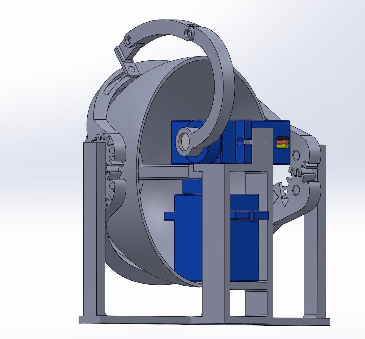
- A central arm connects directly to an SG90 micro servo and rotates the eye left and right.
- Geared eyelids: the eyelids needed to blink without multiple servos or large linkages.
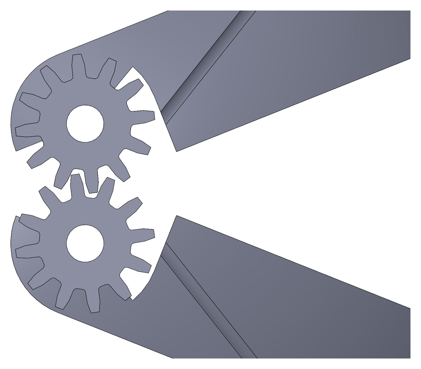
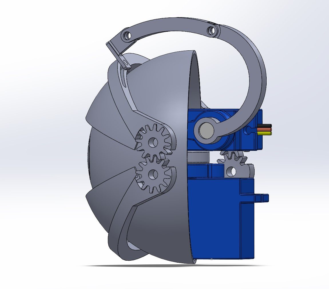
- Custom gears are designed directly into the upper and lower eyelids. The gears mesh, so the lids always open and close together and only one eyelid needs to be driven by a servo.
- Self-contained eyelid drive: the servo needed to mount within the eye cavity.
- The eyelid servo mounts on a frame inside the eye, keeping the whole mechanism compact. A curved two-bar linkage reaches up and over the eyeball to the top of the upper eyelid, shaped to stay clear of the eyeball as it rotates left and right.
Specs (from the final CAD, v3)
- Overall: 80 × 84 × 59 mm including the servo test stand; 10 parts in the final assembly.
- Eyeball: Ø64 mm sphere with a 1.0 mm wall. Eyelids: 72 mm wide, 1.0 mm shells.
- Eyelid gears: a 1:1 spur pair cut into the eyelid hubs, so one servo drives both lids.
- 12 teeth, module 0.8, 20° pressure angle
- Ø9.6 mm pitch, Ø11.2 mm tip, 9.6 mm center distance
- Eyelid linkage: 30.0 mm crank on the lid servo and a curved 26.79 mm coupler (R35 mm arc) that reaches over the eyeball to the upper lid.
- Clearances: lid bores Ø3.0 mm on Ø2.5 mm pivots (0.5 mm diametral clearance); the upper lid has a 1.5 mm slot for the Ø2.0 mm hinge pin.
- Servos: two SG90 micro servos, one for the eyeball and one for the eyelids, both mounted inside the eye.
- Printing: PLA on a Bambu Lab A1, 0.2 mm layers.
Iterations
- First iteration: the print-in-place gears were too small and the teeth fused together. The test stand was not stable enough to support the rotational inertia from the servos.
- CAD v1: 10-tooth gears (Ø7.0 mm tip) with Ø2.5 mm bores on Ø2.5 mm pivots, so zero clearance; 68 mm lids.
- Second iteration: incorrect tolerancing prevented the two-bar linkage from securely connecting to the eyelid. The servos were not properly secured to the test stand.
- CAD v2: 12 teeth at module 0.5 (Ø6.0 mm pitch); bores opened to Ø3.0 mm on the same Ø2.5 mm pivots (0.5 mm clearance).
- Third iteration: resized the gear teeth, added cross braces to the test stand, added a slot to the eyelid, and added screw holes to secure the servos. The mechanism worked, but the linkage joints were too small and broke during assembly. I repaired them with duct tape; this repaired third iteration is the eye in the video.
- CAD v3: same 12 teeth scaled up to module 0.8 (Ø9.6 mm pitch, pivots 6.0 → 9.6 mm apart); lids widened 68 → 72 mm.
Code
- Arduino C++, adapted from a SparkFun Inventor's Kit servo example (Circuit 3A).
- Three push buttons: look left, look right and blink.
- Look: the eyeball servo moves between 40° and 140° (a 100° sweep). While a button is held, each 10 ms step covers 5% of the remaining distance, so the eye starts fast and eases into the end position.
- Blink: the lid servo goes from 20° to 70°. Each 10 ms step multiplies the angle by 1.1 to close and divides by 1.1 to open, which gives an eased motion. Computed from the code: about 140 ms to close, a 100 ms hold and about 140 ms to open, so one blink takes about 0.4 s.
Result
- A working animatronic eye, about 3 in at the base, that blinks and looks left and right with two SG90 micro servos mounted inside the eye.
- The eye has since been taken apart. The video, the SolidWorks files and the Arduino sketch are the record of the build.
What I'd improve next
- Increase the outer diameter of the linkage joints so they do not break when the pins are inserted.
- Fix an overshoot bug in the blink: the close loop stops only after the angle passes 70°, so the last ×1.1 step reaches about 76°. The loop should clamp the angle to the 70° limit.
- Add running clearance where the CAD is line-to-line: the Ø2.0 mm hinge pin sits in a Ø2.0 mm hole, and the eyelid shells (R32 mm inside) sit on the eyeball (R32 mm outside).
What I learned
- Advanced assemblies in SolidWorks
- Designing linkages and slots for dynamic motion and simpler assembly
- Creating organic servo motion with custom Arduino code