Team project · ME 4550
BenchPress: Automated Folding Picnic Table
- Problem
- Design a folding picnic table whose legs fold out with a hand crank and gearbox (no motor).
- Date
- Summer 2026
- Team
- 5 students; Prof. Hashemi; report dated 06/04/2026
- My role
- Frame and brace analysis (stress, buckling, fatigue), frame-to-brace bolt, all CAD and 3D printing
- Design loads
- 1000 lb total; safety factor 2
- Tools
- Hand calculations, SolidWorks, 3D printing
This was a class design project. No physical prototype was built or tested. The numbers below come from hand calculations in the team's final report.
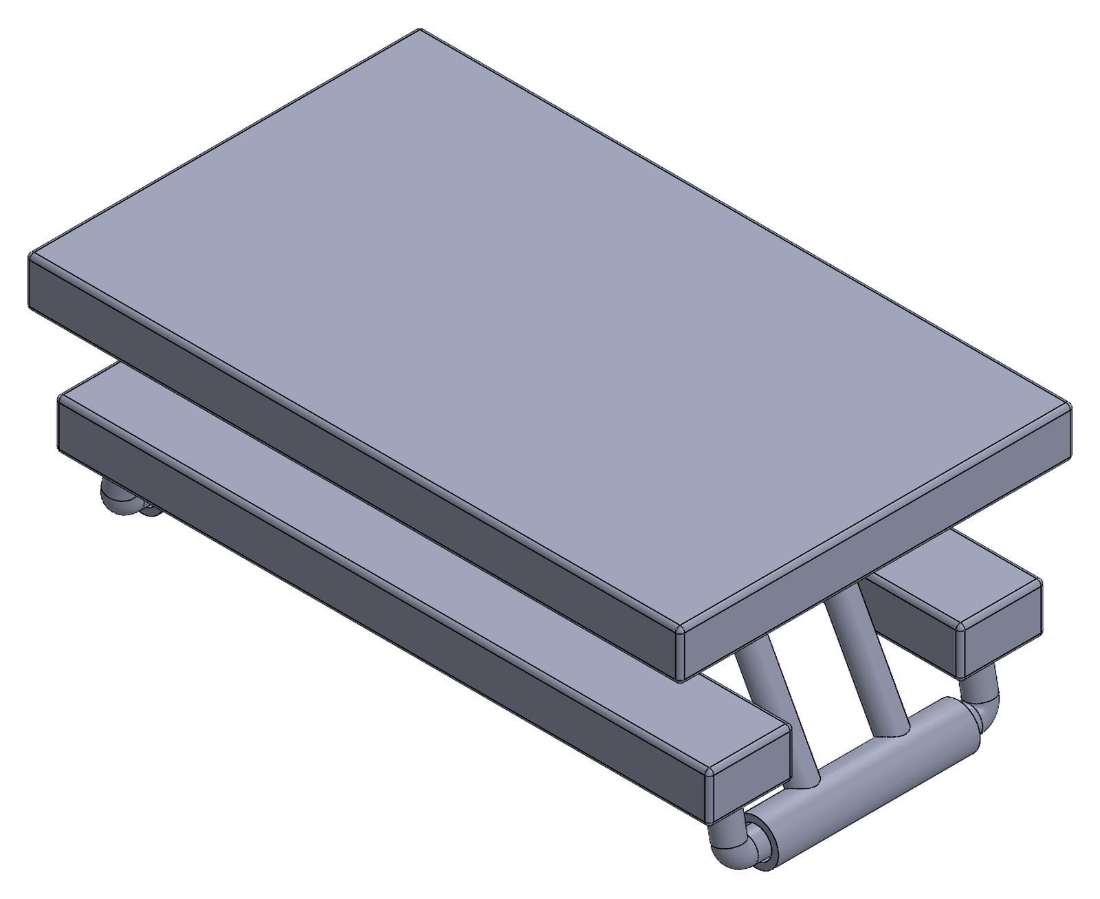
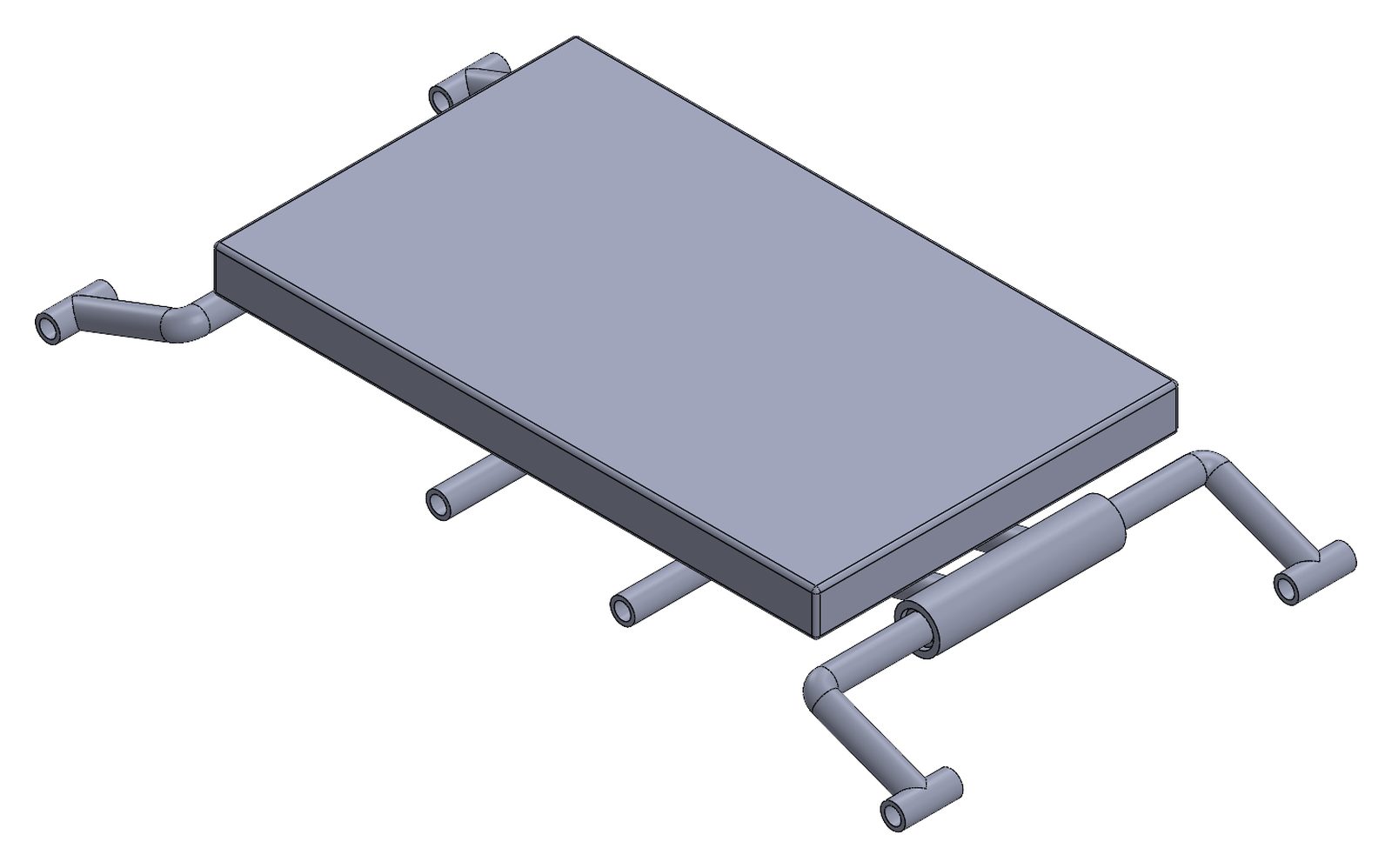
The design
- A 72 in × 30 in tabletop with two 72 in benches. The legs swing out from the folded position.
- A 6 in hand crank drives a 2-stage spur gearbox to raise the legs. The input is set at 5 lbf, the ADA minimum force to open a door.
- Design assumptions: at most 1000 lb on the table and benches, and a safety factor of 2.
My part: frame and brace stress and buckling (report §2.1)
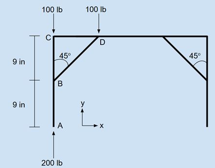
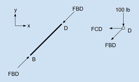
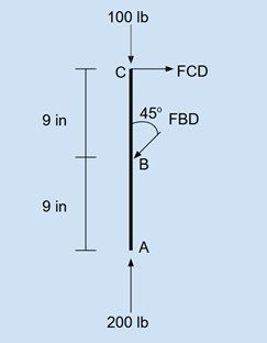
- Drew the free-body diagrams of the bench frame and its 45° brace. Each side of the frame carries one 200 lb point load; I analyzed one side by symmetry.
- Brace: a 1 in × 0.125 in bar at 45°, treated as a two-force member.
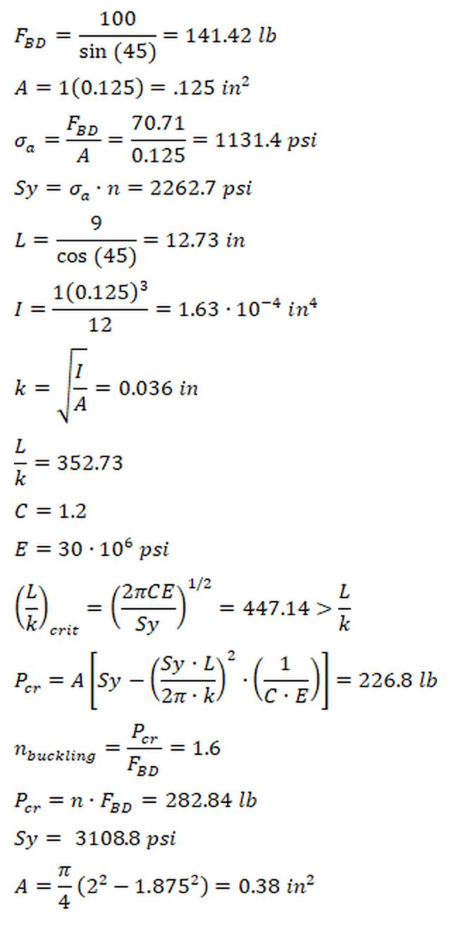
- Brace force F_BD = 100 / sin 45° = 141.42 lb; axial stress 1131.4 psi.
- Johnson column buckling with the ends treated as fixed (it buckles out of plane, C = 1.2): P_cr = 226.8 lb, so the buckling safety factor was only 1.6, below the required 2.
- I then set P_cr = 2 × F_BD = 282.84 lb and solved Johnson's equation for the yield strength the brace material needs: Sy = 3108.8 psi.
- Frame: a hollow steel tube, 2 in OD and 1.875 in ID.
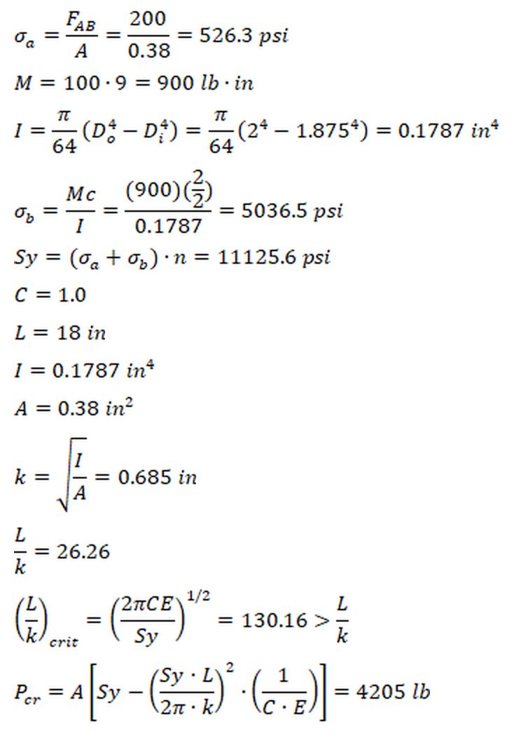
- Combined axial (526.3 psi) and bending stress from the brace (5036.5 psi) gives a required Sy of 11,125.6 psi at SF 2.
- Johnson buckling of the 18 in section: P_cr = 4205 lb, far above the 200 lb load.
My part: fatigue and material selection (report §2.2)
- Load case: people sitting down and standing up, so the load cycles 0 → 200 lb per person. Designed for infinite life.
- Applied Marin factors to the endurance limit and used the modified Goodman criterion with n = 2.
- Required ultimate strength: 5551 psi for the brace and 32,047 psi for the frame. Fatigue, not static stress, drove the frame material.
- Selected AISI 1006 hot-rolled steel for the frame (Sut 43 ksi, Sy 24 ksi) and 2017-O aluminum for the brace (Sut 26 ksi, Sy 10 ksi).
My part: frame-to-brace bolt (report §3.3)
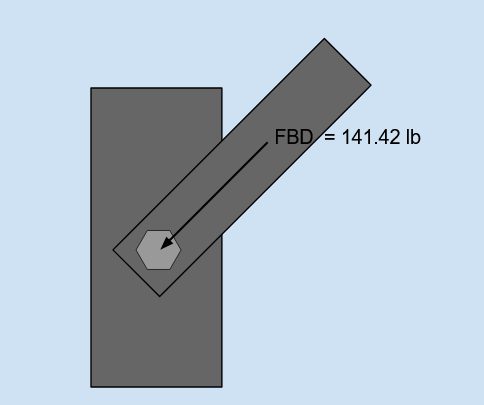
- A 1/4 in-28 UNF bolt in pure shear carries the 141.42 lb brace force. I sized its length (2.25 in) and thread length from the grip.
- Shear stress 4338 psi. A Grade 5 bolt gives a safety factor of 12.24, far more than needed.
- Downgraded to Grade 1 (n = 4.8), which still clears the SF 2 target and costs less.
My part: CAD and 3D printing
- Modeled all the team's SolidWorks parts and assemblies: bench arm, table arm, tabletop, bench seat and the full assembly (a scaled model, 146.9 × 58.9 × 88 mm, 7 parts).
- Did all the 3D printing: a test arm, test cylinders and arm caps in several sizes. The v2 table arm opened the pivot bore from Ø7 to Ø8 mm.
Team work (not my sections)
- Teammates designed the hand-crank 2-stage gearbox (12T → 60T spur stages), sized the tabletop and bench seats, and checked the welds and the tabletop bolts.
What I'd check next
- Re-run the brace buckling check with aluminum's modulus. The check assumed steel (E = 30 × 10⁶ psi), but 2017-O aluminum (about 10.5 × 10⁶ psi) was chosen later for fatigue. If it falls short, switch to a steel brace or a thicker bar.
- Build and load-test a full-size frame and brace. Nothing in this project was physically tested.